JXD-R6-E1ETH (v1) controller

General description
The modular controller JXD-R6-E1ETH (v1) is designed to handle a wide range of tasks in home and industrial automation, as well as monitoring and control of technological processes. The controllers can be used both in local automation systems and as part of distributed systems. The built-in Ethernet communication interface allows the controller to be connected to an existing local area network.
The controller has six power relays with changeover contact (up to 10 A at 250 V AC or 30 V DC) with individual galvanic isolation of outputs, six discrete inputs with group galvanic isolation (common contact COM) for sensors of type dry contact and an input for connecting 1-Wire sensors. For communication, a wired Ethernet 10/100 Mbit/s interface and wireless Wi-Fi and Bluetooth interfaces are provided. The graphic display on the front panel (available depending on configuration) allows displaying the controller state and conveniently configuring controller parameters.
Basic controller functions:
Control of power loads using relays.
Polling sensors with discrete output “dry contact”.
Polling 1-Wire sensors.
Measurement of its own supply voltage.
Temperature measurement inside the enclosure.
Built-in real-time clock with independent power from a CR1225 battery.
Data transmission via Ethernet, Wi-Fi, and Bluetooth.
Displaying status and configuring parameters using a display with joystick and buttons (depending on configuration).
Peripheral expansion with internal JetHome JXM extension modules installed in the controller enclosure.
Peripheral expansion with external JetHome JXDIO extension modules connected via the external I2C bus.
Controller functions can be expanded with additional extension modules: internal JetHome JXM modules installed in the controller enclosure, and external JetHome JXDIO modules installed on a DIN rail next to the controller. The controller operating logic depends on the installed user firmware.
The standard DIN-rail enclosure allows the controller to be conveniently placed in an electrical panel.
Application areas
The controller is designed for local control of electrical loads based on wired sensor states, schedules, and network commands. Typical application scenarios:
Lighting control. Lighting groups connect to relay outputs, and rocker switches, buttons, and motion sensors with an output of the dry contact type - to discrete inputs. Individual galvanic isolation of relay outputs allows switching groups powered from different lines.
Thermostat, heating control. Temperature is monitored by 1-Wire sensors. Actuators – boiler, circulation pumps, electric drives for valves and manifolds – are connected to relay outputs. The built-in real-time clock enables scheduled temperature modes.
Ventilation and climate control. Stepped control of fans, damper actuators, and heaters based on sensor states.
Control of pump equipment and water supply. Pump control based on signals from float level sensors and pressure switches with a “dry contact” output.
Security and technical monitoring. Polling of leak sensors, door and window opening, limit switches, and emergency contacts of equipment with event transmission to the upper-level system.
Building engineering equipment dispatching. Collecting equipment status and transmitting data via Ethernet or Wi-Fi, including as a remote input/output node within a distributed system.
The controller is designed for installation in an electrical panel and can be used at the following facilities:
Apartments, private houses, and cottages.
Office and retail spaces, cafes, hotels.
Warehouses, workshops, garages, and parking areas.
Boiler rooms, pumping stations, individual heating points.
Greenhouses, orangeries, winter gardens.
Server and technical rooms.
Design
The JXD-R6-E1ETH (v1) controller has a modular design.
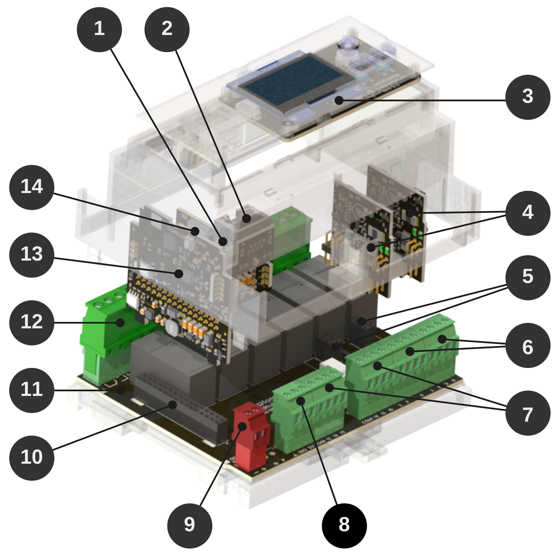
Controller composition and elements:
User button
FNon the front panel of the controller.Ethernet RJ45 connector on the front panel of the controller.
OLED display module with buttons on the controller’s front panel.
Two peripheral expansion modules JXM.
Connectors for JXM modules on the motherboard.
External terminals
JXM1andJXM2for outputting signals from expansion modules.Discrete input terminals
DIGITAL INPUTS.1-WIREterminal.DC INpower supply terminal.32-pin processor module connector on the motherboard.
Motherboard.
Relay terminals
RELAY 1, …RELAY 6.Processor module.
USB Type-C console connector
CONSOLEon the front panel of the controller.
Processor and memory
Dual-core microcontroller ESP32-D0WD-V3.
Core frequency up to 240 MHz.
External SPI NOR-Flash with a capacity of 16 MB.
520 KB of RAM built into the microcontroller.
External SPI PSRAM, 8 MB (installed depending on configuration).
I2C FRAM 8 KB (installed depending on configuration).
I2C EEPROM 8 KB.
Enclosure
The JXD-R6-E1ETH (v1) controller is housed in a GAINTA D6MG enclosure and is designed for mounting on a standard 35 mm DIN rail. The enclosure material is polycarbonate/ABS UL94-V0. The enclosure protection rating is IP20 per GOST 14254-2015. Enclosure drawing GAINTA D6MG
Dimensions and weight
Overall enclosure dimensions - 106.25 x 90.2 x 57.5 mm.
The enclosure width is approximately 6 standard modules for a DIN rail (17.5 mm).
Controller weight in the configuration: processor module, motherboard, display module, without JXM modules - 300 g.
Equipment options
The controller is available in two configuration variants:
JXD-R6-E1ETH - base configuration: without display module, without PSRAM and FRAM memory chips.
JXD-R6-E1ETH-LCD - extended configuration: with display module with joystick and buttons, PSRAM and FRAM memory chips.
Revisions
The JXD-R6-E1ETH (v1) controller is equipped with a JXD-CPU-E1ETH processor module revision 1.x and a JXD-D6-R6 motherboard revision 1.x.
Processor module revisions
v1.4
Initial module version
Motherboard revisions
v1.4
Added external I2C bus
Added the optional capability to install an additional connector on the side wall of the enclosure for routing out the external I2C bus
v1.3
Added optional ability to install an additional linear stabilizer
Added test points for extended board testing
v1.2
Initial board version
Interfaces
Wi-Fi/Bluetooth
The ESP32 microcontroller includes a built-in Wi-Fi/Bluetooth wireless module:
Wi-Fi 802.11b/g/n (2.4 GHz), data transfer rate up to 150 Mbps.
Bluetooth v4.2 BR/EDR with support for BLE specification.
The processor module has a ceramic antenna for the 2.4GHz band. It is possible to connect an external antenna via the U.FL connector, also located on the processor module.
Ethernet
The controller uses an IEEE-802.3-compatible ethernet MAC interface built into the ESP32 microcontroller. Data transfer rates of 10/100 Mbps are supported.
The Ethernet PHY is a LAN8720A chip connected to the ESP32 microcontroller via the RMII interface.
Main characteristics PHY
Data transfer rates of 10 and 100 Mbps are supported.
Half-duplex and full-duplex modes of operation are supported.
The processor module connects the Ethernet PHY chip without an additional crystal resonator or oscillator.
The 50 MHz clock pulses required for the Ethernet PHY chip are generated by the ESP32 microcontroller itself.
Wiring diagram
The Ethernet PHY chip is connected to the following pins of the ESP32 microcontroller:
ESP32 output |
Function |
|---|---|
GPIO25 |
ETH_RXD0 |
GPIO26 |
ETH_RXD1 |
GPIO27 |
ETH_CRS_DV |
GPIO19 |
ETH_TXD0 |
GPIO22 |
ETH_TXD1 |
GPIO21 |
ETH_TXDEN |
GPIO23 |
ETH_MDC |
GPIO18 |
ETH_MDIO |
GPIO17 |
50MHZ CLK OUT |
GPIO15 |
ETH_RESET |
The GPIO15 pin of the ESP32 microcontroller is used for hardware reset of the Ethernet PHY chip: logic level 0 - chip reset, logic level 1 - operating mode.
External periphery
Display
A display module with a joystick and buttons can be installed on the front panel of the controller. The display allows you to show the state of the controller, as well as configure the controller parameters. The information displayed on the display and the assignment of the display buttons depend on the software installed on the controller.
Note
The display module is installed depending on the configuration of the controller.
The display module has a monochrome OLED screen with a 1.3-inch diagonal and a resolution of 128x64 pixels. The screen is connected to the internal I2C bus, the address of the screen on the internal I2C bus is 0x3C.
The display driver is SH1106.
The display module is connected to the processor module using a four-wire cable with Micro JST connectors with a contact pitch of 1.25mm.
Pin assignment of the display module connector:
Pin number |
Destination |
Description |
|---|---|---|
1 |
I2C SCL |
Clock line of the internal I2C bus |
2 |
I2C SDA |
Data line of the internal I2C bus |
3 |
+3,3V |
Display module power supply +3.3V |
4 |
GND |
Common wire |
Display module port expander
The display module has a port expander chip PCA9535 connected to the internal I2C bus.
Port expander chip address on the internal I2C bus - 0x24.
The port expander chip is used to read the states of the joystick and buttons.
Display module expander ports in use
Port |
Function |
Description |
|---|---|---|
8 |
UP |
Joystick contact “Up” |
9 |
DOWN |
Joystick contact “Down” |
10 |
LEFT |
Joystick contact “Left” |
11 |
RIGHT |
Joystick contact “Right” |
12 |
ENTER |
Joystick center contact “Enter/OK” |
13 |
HOME |
Button “Home/Start” |
14 |
BACK |
Button “Back/Cancel” |
The remaining expander ports are not used.
The button states are determined by the following logic levels at the port expander inputs: 0 - button not pressed, 1 - button pressed. The buttons have hardware debouncing using Schmitt triggers.
Relay
The motherboard contains 6 discrete relay outputs with output type Changeover contact and the following characteristics:
Maximum switched current - 10A for resistive load
Maximum switching voltage - 250V AC or 30V DC.
Electrical relay life - 100 000 switching cycles at maximum load.
Relay outputs feature individual galvanic isolation: the outputs of each relay are galvanically isolated from each other.
Optionally, the controller can be equipped with relays with reinforced contacts that withstand an inrush current of up to 80A for 20 ms.
Warning
The relays have no protection against overload or overheating. If the nominal ratings of the relays or the device are exceeded, the relays and the device may be damaged.
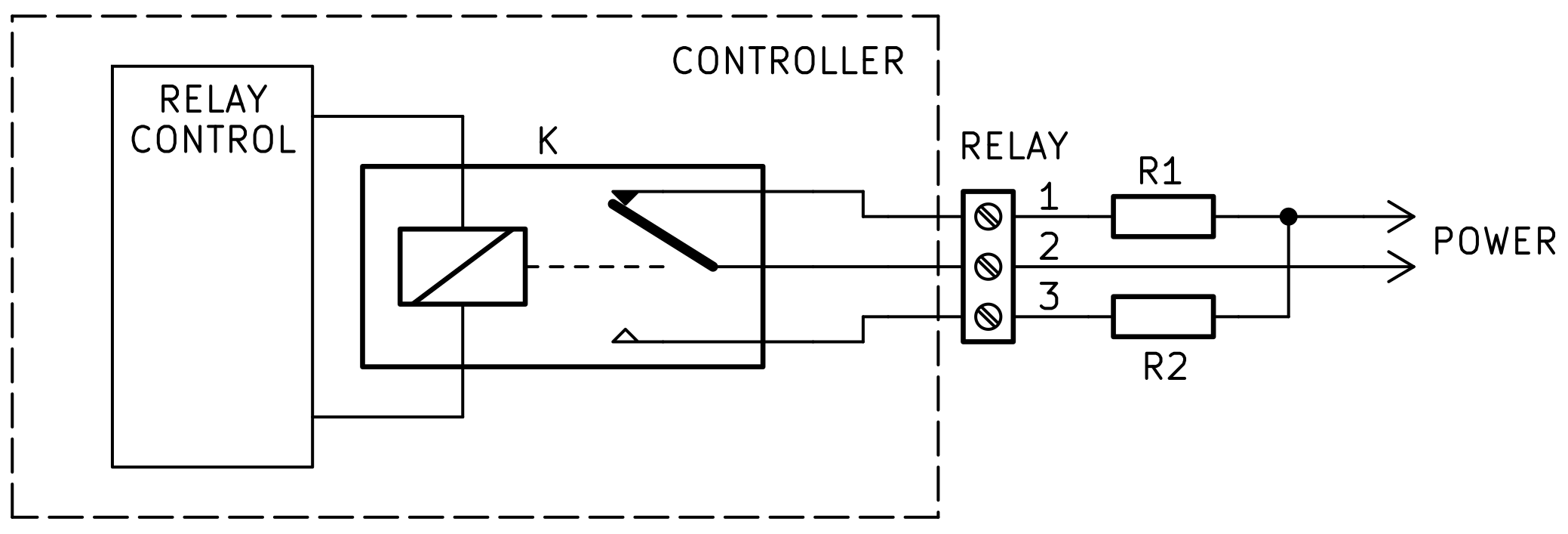
Relay outputs are brought out to three-pin screw terminals RELAY 1, … RELAY 6 with a contact pitch of 5 mm.
The changeover contact allows using the relay output as both a normally open NO and a normally closed NC, as well as to switch the load between two circuits. The individual galvanic isolation of the outputs allows switching loads powered from different lines or different power sources independently of each other.
The relays are controlled via the motherboard’s port extender (see the section GPIO port expanders).
Schematic diagram of the relay output and a possible load connection option (R1 and R2 in the diagram) to the controller’s relay output:
Discrete inputs
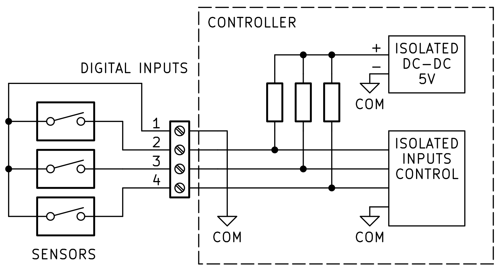
The controller motherboard contains 6 discrete inputs for connecting sensors of type Dry Contact, brought out to two external four-pin screw terminals DIGITAL INPUTS with a contact pitch of 3.5 mm.
Discrete inputs have group galvanic isolation: the inputs are isolated from other elements of the device, but are not isolated from each other and share one common contact COM. Switching of discrete inputs DIGITAL INPUT 1, … DIGITAL INPUT 6 must be done to the common COM contact located on the discrete input terminals. It is not necessary to connect the COM pin to the GND pin on the device.
Discrete inputs provide hardware protection against contact bounce using Schmitt triggers. The internal “pull-up” voltage of the inputs is about 5V. The discrete input current in the closed state is about 5mA.
Discrete input states are read through the motherboard port expander (see section GPIO Port Expanders).
Controller discrete input wiring diagram and connection of sensors with a “dry contact” output to the discrete input terminal:
Devices with an n-p-n transistor output wired in an open-collector configuration can be connected to the discrete inputs. Typical connection diagram for sensors with an n-p-n transistor output:

Purpose of the discrete input terminal contacts:
Pin number |
Destination |
Description |
|---|---|---|
1 |
COM |
Common wire of the discrete inputs |
2 |
INPUT 1 (4) |
Discrete input 1 (4) |
3 |
INPUT 2 (5) |
Discrete input 2 (5) |
4 |
INPUT 3 (6) |
Discrete input 3 (6) |
Pin numbering on the terminal from left to right. Numbers of discrete inputs for the second terminal of discrete inputs are shown in parentheses.
Warning
Be careful when connecting the digital inputs. Do not allow voltage to be applied to the digital inputs, there are pull-up resistors to 5V on the board.
1-Wire
The controller provides the ability to connect external sensors via the 1-Wire bus.
The 1-Wire bus is implemented on the I2C-to-1-Wire converter chip DS2482S-100 mounted on the motherboard.
Address of the DS2482S-100 microchip on the internal I2C bus - 0x18.
The 1-Wire bus timing diagrams are generated by the converter in hardware, without involvement of the microcontroller.
The board has a pull-up resistor on the 1-Wire data line, no additional external pull-up resistors are required. It is recommended to connect 1-Wire sensors using a three-wire scheme (including the power line).
Maximum output current from the power supply terminal 1-WIRE - 0.5 A.
1-Wire connector
For the 1-WIRE terminal, a three-pin screw terminal with a contact pitch of 3,5mm is used.
Pin assignment of the 1-WIRE terminal:
Pin number |
Destination |
Description |
|---|---|---|
1 |
GND |
1-Wire bus common wire |
2 |
DIO |
1-Wire data bus |
3 |
+5V |
Power output +5V (for powering external devices 1-Wire) |
Pin numbering on the 1-WIRE terminal from left to right.
External I2C bus
Note
The external I2C bus is available starting with revision 1.4 of the motherboard.
The external I2C bus is designed for connecting external expansion modules JetHome JXDIO, mounted on a DIN rail next to the controller. The bus and its accompanying interrupt signal are brought out to the following microcontroller pins:
ESP32 output |
Destination |
|---|---|
GPIO13 |
I2C2 SCL |
GPIO14 |
I2C2 SDA |
GPIO36 |
INT |
The external I2C bus is independent of the controller’s internal I2C bus: the buses use different microcontroller pins, so device addresses on the external bus do not conflict with the addresses of the controller’s internal peripherals.
Pull-up resistors are installed on the external I2C bus lines on the motherboard.
Recommended bus frequency: 100kHz (Standard mode) or 400kHz (Fast mode).
External I2C bus connector
The bus is routed to an optional dual-row pin header 2x5 contacts with a pitch of 2.54mm, installed on the side wall of the controller enclosure.
Purpose of the external bus connector pins I2C:
Contact |
Destination |
|---|---|
1 |
DC OUT |
2 |
GND |
3 |
I2C2 SCL |
4 |
I2C2 SDA |
5 |
INT |
6 |
INT |
7 |
I2C2 SDA |
8 |
I2C2 SCL |
9 |
GND |
10 |
DC OUT |
The purpose of the pins is symmetrical about the middle of the connector: pins 1 … 5 are mirrored by pins 10 … 6.
The controller supply voltage is output to the DC OUT pins: the voltage from the DC IN terminal when the controller is powered from an external terminal, or the voltage Passive PoE when the controller is powered from the Ethernet connector.
Maximum current of the supply voltage through the external I2C bus connector - 1A. This must be considered when powering expansion modules from the controller.
The INT pins are connected to the INT pin of the processor module connector in a wired-OR configuration and are intended to provide an interrupt signal from the expansion module to the processor module. The line’s pull-up resistor is installed on the motherboard.
The inner periphery
Memory
FLASH
The processor module has a SPI NOR-Flash memory chip with a capacity of 16 MB. The Flash memory chip is connected to the following pins of the ESP32 microcontroller:
ESP32 output |
Destination |
|---|---|
GPIO6 |
QSPI CLK |
GPIO7 |
QSPI IO1/DO |
GPIO8 |
QSPI IO0/DI |
GPIO9 |
QSPI IO3/HOLD |
GPIO10 |
QSPI IO2/WP |
GPIO11 |
FLASH CS |
PSRAM
Note
The PSRAM memory chip is installed depending on the controller configuration.
The processor module has a SPI PSRAM memory chip with a capacity of 8 MB. The memory chip is connected to the following pins of the ESP32 microcontroller:
ESP32 output |
Destination |
|---|---|
GPIO6 |
QSPI CLK |
GPIO7 |
QSPI IO1/DO |
GPIO8 |
QSPI IO0/DI |
GPIO9 |
QSPI IO3/HOLD |
GPIO10 |
QSPI IO2/WP |
GPIO16 |
PSRAM CS |
Internal I2C bus
The internal I2C bus is used to connect the processor module peripherals and is routed to the following pins of the microcontroller:
ESP32 output |
Destination |
|---|---|
GPIO4 |
I2C SCL |
GPIO5 |
I2C SDA |
Recommended bus frequency: 100kHz (Standard mode) or 400kHz (Fast mode). These modes are supported by most peripheral chips.
The internal I2C bus is also routed to the 32-pin processor module connector and can be used to connect motherboard peripherals.
EEPROM
Processor module EEPROM
The processor module has a non-volatile EEPROM memory chip AT24C64 (or equivalent) of 64Kbit (8 KBytes).
The purpose of this memory is to store the hardware configuration of the processor module.
The address of the memory chip on the internal I2C bus is 0x54.
Motherboard EEPROM
A non-volatile EEPROM memory chip AT24C64 (or equivalent) with a capacity of 64 Kbit (8 KB) is installed on the motherboard.
The purpose of this memory is to store the hardware configuration of the motherboard or other user data (depends on installed software).
The address of the memory chip on the internal I2C bus is 0x56.
FRAM
Note
The FRAM memory chip is installed depending on the controller configuration.
The processor module has a non-volatile FRAM memory chip FM24CL64 (or equivalent) with a capacity of 64 Kbit (8 KB).
This chip supports a large number of rewrite cycles. The purpose of this memory is to store frequently changing data: controller parameter states and other user data.
The address of the memory chip on the internal I2C bus is 0x55.
Real Time Clock (RTC)
The processor module has a real-time clock chip PCF8563 (or analog).
The chip is connected to the internal I2C bus of the module. The address of the chip on the internal I2C bus is 0x51.
To power the RTC, a CR1225 coin cell battery with a voltage of 3V is installed on the processor module board.
See also
Temperature sensor
The processor module has an I2C temperature sensor chip TMP102, which measures the temperature inside the controller enclosure.
The temperature sensor chip is connected to the internal I2C bus of the processor module. The address of the chip on the internal I2C bus is 0x48.
Supply voltage measurement
The processor module can measure the input supply voltages. The measurement is performed by the built-in ADC of the ESP32 microcontroller with a preliminary voltage divider with a ratio of 1:32. The voltage measurement accuracy is about 3%.
Two voltage measurement channels are provided:
Voltage on the DC IN power terminal. The
GPIO35input is used - channelADC_CH7of the ESP32 microcontroller.Passive PoE supply voltage on the RJ45 Ethernet connector. The
GPIO37input is used - channelADC_CH1of the ESP32 microcontroller.
GPIO port expanders
Motherboard port expander
The port expander chip is used to control relays and read the status of the controller’s digital inputs.
A PCA9535 chip connected to the internal I2C bus is installed on the motherboard as a port expander.
The address of the port expander on the internal I2C bus is 0x22.
The interrupt output of the port expander microchip is connected to the INT pin of the processor module connector – the GPIO36 terminal of the ESP32 microcontroller. Using the interrupt signal is optional: the port expander state can be polled via the I2C bus.
Motherboard expander ports in use
Port |
Function |
Description |
|---|---|---|
0 |
RELAY 1 |
Relay 1 control output |
1 |
RELAY 2 |
Relay 2 control output |
2 |
RELAY 3 |
Relay control output 3 |
3 |
RELAY 4 |
Relay control output 4 |
4 |
RELAY 5 |
Relay control output 5 |
5 |
RELAY 6 |
Relay 6 control output |
6 |
JXM1 RESET |
Hardware reset output of module JXM1 |
7 |
JXM1 MODE |
Mode switch output of module JXM1 |
8 |
INPUT 1 |
Discrete input 1 |
9 |
INPUT 2 |
Discrete input 2 |
10 |
INPUT 3 |
Discrete input 3 |
11 |
INPUT 4 |
Discrete input 4 |
12 |
INPUT 5 |
Discrete input 5 |
13 |
INPUT 6 |
Discrete input 6 |
14 |
JXM2 RESET |
Hardware reset output of module JXM2 |
15 |
JXM2 MODE |
Mode switch output of module JXM2 |
Relay control logic: logic level 0 - relay off, logic level 1 - relay on. By default, after power-up the port expander outputs are set to the logic level 0 (relays are off).
The state of the discrete input is determined by the following logic levels at the port expander inputs: 0 - input open, 1 - input closed.
Internal connectors
32-pin processor module connector
A two-row pin header connector with 32 contacts and a contact pitch of 2.54 mm is used to connect the JXD-CPU-E1ETH processor module to the motherboard. Some contacts of the connector are reserved for other purposes and are not used in this processor module.

Contact |
Destination |
Description |
|---|---|---|
1 |
Not used. |
|
2 |
Not used. |
|
3 |
+PoE OUT |
Passive PoE voltage output from the Ethernet connector of the processor module. |
4 |
Not used. |
|
5 |
+DC IN |
Supply voltage input from the motherboard. |
6 |
GND |
General. |
7 |
+5V OUT |
5V voltage output from the processor module. |
8 |
GND |
General. |
9 |
+3.3V OUT |
3.3V voltage output from the processor module. |
10 |
GND |
General. |
11 |
UART1_TX |
UART1 TX output. Connected to the GPIO33 pin of the ESP32. |
12 |
UART1_RX |
UART1 RX input. Connected to the GPIO34 pin of the ESP32. |
13 |
UART2_TX |
UART2 TX output. Connected to the GPIO32 pin of the ESP32. |
14 |
UART2_RX |
UART2 RX input. Connected to the GPIO39 pin of the ESP32. |
15 |
I2C_SCL |
Clock line of the internal I2C bus. Connected to the GPIO4 pin of the ESP32. |
16 |
I2C_SDA |
Data line of the internal I2C bus. Connected to the GPIO5 pin of the ESP32. |
17 |
IO1 |
Input/output. Connected to the GPIO13 pin of the ESP32. |
18 |
IO2 |
Input/output. Connected to the GPIO12 pin of the ESP32. |
19 |
IO3 |
Input/output. Connected to the GPIO14 pin of the ESP32. |
20 |
Not used. |
|
21 |
Not used. |
|
22 |
INT |
External interrupt input from the motherboard to the processor module. Connected to the GPIO36 pin of the ESP32. |
23 |
Not used. |
|
24 |
Not used. |
|
25 |
Not used. |
|
26 |
Not used. |
|
27 |
Not used. |
|
28 |
Not used. |
|
29 |
Not used. |
|
30 |
Not used. |
|
31 |
Not used. |
|
32 |
Not used. |
32-pin motherboard connector
To connect the processor module to the JXD-D6-R6 motherboard, a dual-row pin header with 32 contacts and a contact pitch of 2.54 mm is used. Some contacts of this connector are reserved for other purposes and are not used on this motherboard.

The UART interfaces of the processor module are brought out to the connectors of the expansion modules: UART1 – to connector JXM1, UART2 – to connector JXM2.
Contact |
Destination |
Description |
|---|---|---|
1 |
Not used. |
|
2 |
Not used. |
|
3 |
+PoE IN |
Passive PoE voltage input from the Ethernet connector of the processor module. |
4 |
Not used. |
|
5 |
+DC OUT |
Supply voltage output from the motherboard. |
6 |
GND |
General. |
7 |
+5V IN |
5V voltage input from the processor module. |
8 |
GND |
General. |
9 |
+3.3V IN |
3.3V voltage input from the processor module. |
10 |
GND |
General. |
11 |
CPU_UART1_TX |
UART1 TX input for data transfer from the processor module to the motherboard. Connected to the JXM1 module connector. |
12 |
CPU_UART1_RX |
UART1 RX output for data transfer from the motherboard to the processor module. Connected to the JXM1 module connector. |
13 |
CPU_UART2_TX |
UART2 TX input for data transfer from the processor module to the motherboard. Connected to the JXM2 module connector. |
14 |
CPU_UART2_RX |
UART2 RX output for data transfer from the motherboard to the processor module. Connected to the JXM2 module connector. |
15 |
I2C1_SCL |
Clock line of the internal I2C bus. Connected to the internal peripherals of the motherboard. |
16 |
I2C1_SDA |
Data line of the internal I2C bus. Connected to the internal peripherals of the motherboard. |
17 |
I2C2_SCL (v1.4) |
Clock line of the external I2C bus. Starting from motherboard revision 1.4. |
18 |
Not used. |
|
19 |
I2C2_SDA (v1.4) |
Data line of the external I2C bus. Starting from motherboard revision 1.4. |
20 |
Not used. |
|
21 |
Not used. |
|
22 |
INT OUT |
Interrupt output from the motherboard port expander. A pull-up resistor is installed on the board. |
23 |
Not used. |
|
24 |
Not used. |
|
25 |
Not used. |
|
26 |
Not used. |
|
27 |
Not used. |
|
28 |
Not used. |
|
29 |
Not used. |
|
30 |
Not used. |
|
31 |
Not used. |
|
32 |
Not used. |
Motherboard JXM expansion module connectors
To connect JXM expansion modules to the motherboard, two dual-row pin headers are used: 6 pins JXM IO and 4 pins JXM EXT with a contact pitch of 2.54 mm. The 6-pin JXM IO connector is used to power the module and connect it to the processor via the UART interface. The 4-pin JXM EXT connector is used to output signals from the expansion module to the external 4-position screw terminal.

Contact |
Destination |
Description |
|---|---|---|
1 |
+5V OUT |
5V output for powering JXM modules. |
2 |
GND |
General. |
3 |
CPU_UART_RX |
UART RX line input for data transfer from the JXM module to the processor module. |
4 |
CPU_UART_TX |
UART TX line output for data transfer from the processor module to the JXM expansion module. |
5 |
RESET |
Hardware reset output of the JXM module. Output type: “open collector”. |
6 |
MODE |
Operating or boot mode switch output of the JXM module. Output type: “open collector” on the motherboard. |

Contact |
Destination |
Description |
|---|---|---|
1 |
IO1 |
Input/output to pin 1 of the external JXM terminal. |
2 |
IO4 |
Input/output to pin 4 of the external JXM terminal. |
3 |
IO2 |
Input/output to pin 2 of the external JXM terminal. |
4 |
IO3 |
Input/output to pin 3 of the external JXM terminal. |
Screw terminals with a contact pitch of 3.5 mm are used as external terminals for the JXM1 and JXM2 modules. The pin numbering of the external JXM screw terminal is from left to right.
The pins of the JXM IO connectors of slots JXM1 and JXM2 are connected to different pins of the microcontroller and to different ports of the motherboard port expander (address 0x22):
Pin assignment of the connector JXM IO of slot JXM1:
Contact |
Destination |
Connection |
|---|---|---|
1 |
+5V OUT |
Module power supply +5V |
2 |
GND |
Common wire |
3 |
CPU_UART_RX |
Pin |
4 |
CPU_UART_TX |
Pin |
5 |
RESET |
Port |
6 |
MODE |
Port |
Pin assignment of the connector JXM IO slot JXM2:
Contact |
Destination |
Connection |
|---|---|---|
1 |
+5V OUT |
Module power supply +5V |
2 |
GND |
Common wire |
3 |
CPU_UART_RX |
Pin |
4 |
CPU_UART_TX |
Pin |
5 |
RESET |
Port |
6 |
MODE |
Port |
Note
The JXM EXT connector is identical for both slots: its pins are not connected to the microcontroller and are brought out to the external screw terminal of the corresponding module.
Console
The processor module board has a USB-UART interface converter based on the CP2102 chip, and the USB Type-C connector to which this converter is connected is brought out to the front panel of the controller.
For console connection, the GPIO1 - UART0_TX and GPIO3 - UART0_RX pins of the ESP32 microcontroller are used.
The RTS and DTR signals of the UART interface are used to automatically reset the microcontroller and switch it to firmware loading mode. Standard utilities for flashing ESP32 microcontrollers can be used for this purpose.
Power
The following power supply options are available:
From an external stabilized DC power source through the external red screw terminal with 3.5 mm contact pitch on the motherboard.
Note
Recommended (rated) input voltage range 12V to 48V.
Maximum allowable input voltage 36V.
Via Passive PoE through the RJ45 connector of the processor module Ethernet port.
Note
Recommended rated input supply voltage Passive PoE - from 12V to 24V.
Maximum allowable input voltage 36V.
The polarity of the connection does not matter. Recommended power supply scheme: “+” of the power supply to pins 4 and 5, “-” of the power supply to pins 7 and 8 of the Ethernet connector.
Voltage drop on long lines must be considered, and a power supply with a higher output voltage should be selected. For powering the controller via Passive PoE technology, it is recommended to use a 24 V power supply.
Note
If power is applied to both the external terminal and the Ethernet connector at the same time, power will be supplied from a high voltage source. It is recommended to use one of the power supply options.
The power consumption of the controller without additional JXM modules is up to 3 W. When additional expansion modules are installed, the power consumed by the controller can increase significantly. This must be considered when selecting a power supply for the controller.
To power the controller, it is recommended to use a stabilized DC power supply with a power of at least 5W.
When using additional JXM modules and powering external devices and sensors from the +5V pin of the 1-WIRE terminal, it is recommended to use a power supply with a capacity of at least 10 W.
Warning
There is no galvanic isolation of the power supply circuits in the controller.
Software
See also
Officially supported software:
ESPHome - ESP32 firmware to work with Home Assistant.
ESP-IDF - official SDK from Espressif for development on ESP32.
Note
It is also possible to use any other software for ESP32: Tasmota, Arduino and others.
Controller firmware
The ESP32 microcontroller can be flashed over the dedicated UART0 interface (pins GPIO1 and GPIO3 of the ESP32 microcontroller).
To flash, simply connect the processor module board to the computer via USB using the USB Type-C connector on the front panel of the controller.
Note
When using standard tools for flashing ESP32 microcontrollers the switch to the bootloader mode is made automatically when flashing.
Note
The processor module can be powered from the USB Type-C connector during flashing.
The controller motherboard will not be powered in this case.
Safety precautions
The device shall be operated and maintained in accordance with applicable electrical safety standards and the national and local regulations governing the operation of electrical installations and occupational health and safety in the country of use.
All connections to the device and maintenance work shall be performed only with the device power disconnected and the actuators connected to it de-energized.
Physical access to the device during installation and maintenance shall be restricted to qualified service personnel.
Moisture must not be allowed to come into contact with the output connector pins or the internal components of the device.
The device must not be used in atmospheres containing acids, alkalis, oils, or other corrosive substances.
The device is not intended for use in environments that may pose a risk to the life and health of persons nearby.
If the device has an Ethernet interface, it must not be connected to a local network with access to the Internet without reliable network protection measures.
Mounting
Note
When installing the device, the power equipment in the cabinet must be de-energized.
The unit can be installed in an electrical equipment cabinet or other location, where it must be protected from moisture, dirt and foreign objects, as well as vibration-free.
Note
For better cooling of the internal components, the housing should be installed in an upright position.
To install it, you have to:
Make sure there is enough space to connect the device and run the wires.
Securely fasten the unit to the DIN rail or to a vertical surface with screws.
To remove it from the DIN-rail you should:
Insert the tip of a screwdriver into the latch eyelet.
Press the latch down.
Remove the device from the DIN rail.
Operating conditions
Ambient temperature: 0..+40 С.
Relative humidity up to 80% without condensation.
Closed explosion-proof rooms without aggressive vapors and gases.
The resistance to climatic effects meets category UHL4 according to GOST 15150-69.
Wiring recommendations
To ensure reliable electrical connections, it is recommended to use copper stranded cables. The cable ends should be stripped, then tinned or fitted with cable ferrules. The cable conductors should be stripped so that their exposed ends do not protrude beyond the terminal block after connection to the device.
General requirements for connection lines:
When laying the cables, the communication lines that connect the device to the sensors or other devices should be separated into separate routes, and located separately from power cables and cables that cause high-frequency and pulse interference.
To protect the device inputs from electromagnetic interference on the communication line, shielding should be used. Shields can be made using special cables with shielding braids.
It is recommended to install mains interference filters in the device power supply line.
In the case of controlling power equipment, it is recommended that spark-quenching filters be installed on the switching line of this equipment.
Limitations
Warning
The device is not intended for use in facilities potentially endangering the life and health of others, as well as life support systems and other critical systems.
Useful Links
The ESP32 Pin list is a list of ESP32 pins and their functions.